App Note: Optimizing 4-Channel Color Mixing Systems for Color Rendering
March 21, 2023Optimizing 4-Channel Color Mixing Systems for Color Rendering
By Derek Miller, XLamp® R&D Research Scientist, Cree LED
Introduction
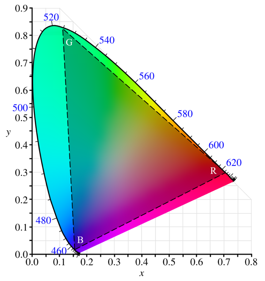
Color mixing systems with LEDs commonly use either a 3- or 4-channel approach. With 3 channels, using red, green and royal blue is the most common way to cover the widest range of possible colors. With a 4-channel approach, luminaire designers often opt to add a white LED (2700K to 7500K CCT, near the black body line). White lies within the achievable range of the 3-channel RGB solution but adding a phosphor-converted white LED gives a more balanced spectrum and often better color rendering. Further, it allows the device to operate in an easy 1-channel mode to produce good quality white light.
Cree LED has introduced the XLamp® Element G (XE-G) high-power and J Series® 2835 mid-power color LED families, offering up to 17 color options plus the full range of white CCT and CRI options. These new color options enable new 4-channel color-tunable solutions with higher LPW and more accurate color rendering than what could previously be achieved.
This application note explores the advantages and disadvantages of using different LED colors as the fourth channel in a 4-channel system, supplementing the existing three channels of red, green and royal blue. All the scenarios explored in this application note were optimized to achieve the highest possible CRI Ra across a standard range of white light CCT targets near the BBL. Different optimizations, such as maximizing LPW or CRI R9, are possible and may be more suited for your application.
Test Methods
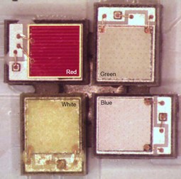
Four XLamp XE-G LEDs were individually controlled using separate power supplies by setting the drive current of each LED so that the total current of the system always totaled to 3 A. The LEDs were arranged on a Rayben MHE 301 MCPCB in a pinwheel configuration with a 200 µm edge-to-edge spacing. More details can be found in the XLamp® Element G (XE-G) LED Design Guide.
The MCPCB was fixed to a thermoelectric cooler (TEC) set to maintain a temperature of 25 °C. Data were collected in an integrating sphere without a secondary optic or diffuser. Data were collected only for configurations that resulted in CRI Ra values of at least 70.
LPW and Color Quality Improvements Using all 4 Channels Simultaneously
In many RGBW applications, customers use the white channel only for white light, and use the RGB channels in a 3-channel mixing mode to access the rest of the color space for non-white light. Our research here has shown that both higher LPW and better color rendering are possible together if all 4 channels are used simultaneously to reach a range of white CCTs and non-white color spaces.
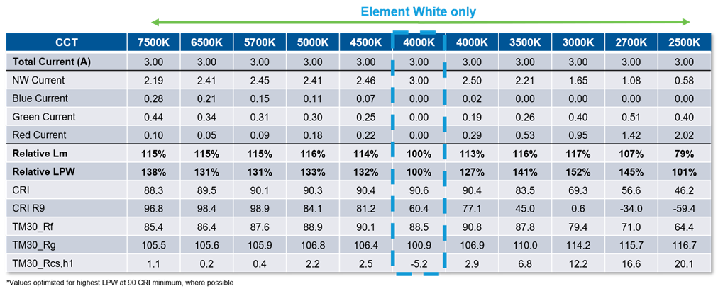
The data in Table 1 below were collected with an RGBW array where a 4000K 90 CRI XE-G LED was used as the white channel. The lumens and LPW are normalized to the center column where only the white LED was energized for 4000K 90 CRI light. LPW improvements of up to 33% can be seen while maintaining a 90 CRI minimum, along with higher CRI R9 scores over most of the CCT range. Higher LPW is achieved by spreading the same total current across four times the epi area, so each chip runs more efficiently. Higher color quality results from a fuller, flatter spectrum. The 4-channel mode also gives better control over color quality specifications such as TM-30.
Lumen Output and LPW Improvements with Non-white Fourth Channel
The next set of data comes from a different experiment where the red, green and blue channels were supplemented with six different colors in the fourth channel: PC mint, PC amber, PC lime, PC yellow, 4000K 90 CRI white and 3000K 90 CRI white.
The first thing noticeable about the total lumen output data shown in Figure 3 is that there are two distinct groups, higher lumens and lower lumens. The lower lumens grouping all use an LED that contains red or amber phosphor. Using phosphor to convert blue photons into amber or red photons (570-700 nm wavelengths) is less efficient than generating those photons directly with an amber or red LED due to Stokes shift and inefficiencies in the conversion process. Even though every system simulated already includes a red LED, a significant portion of the 3 A total current is routed toward the phosphor-converted LED to maximize CRI because that is the optimization target.
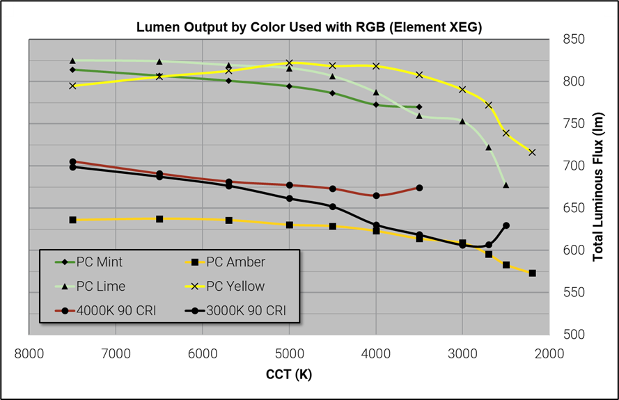
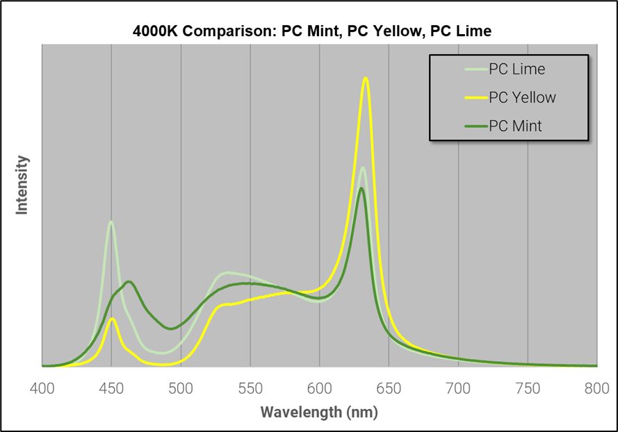
The three LEDs in the higher-lumen group consist of phosphor-converted LEDs that do not have much output in the amber or red wavelengths: PC mint, PC lime and PC yellow. Out of these three colors, PC yellow provides higher lumen output through the warm white (≤3000K CCT) region than PC lime and PC mint, but all three colors are similar at higher CCTs. A spectral comparison is shown for reference in Figure 4.
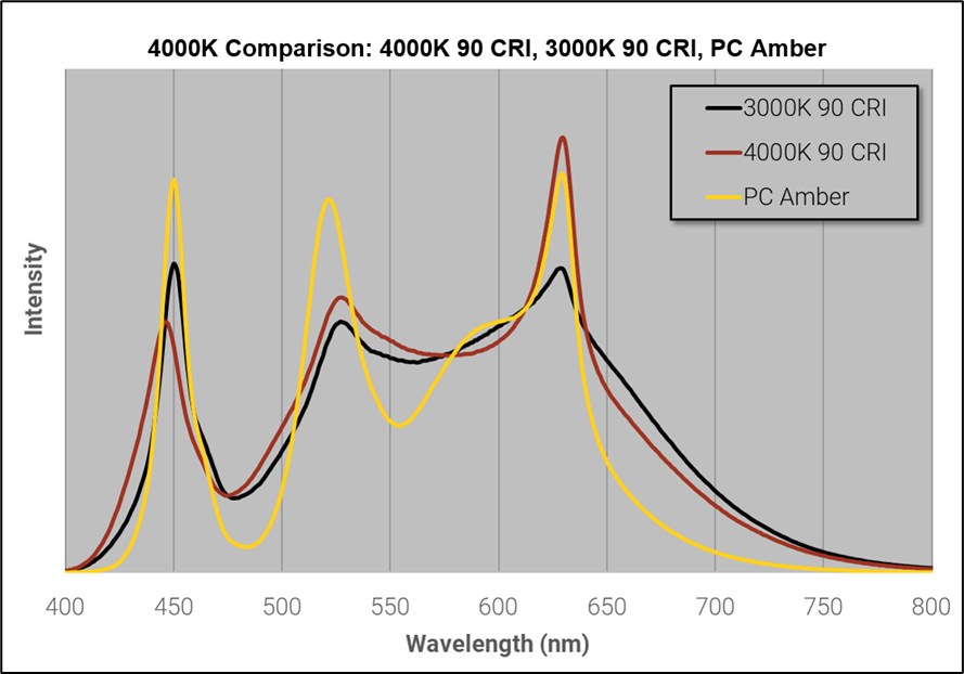
The three LEDs in the lower-lumen group consist of phosphor-converted LEDs with significant output in the amber and red wavelengths: PC amber, 4000K 90 CRI white and 3000K 90 CRI white. Of these three colors, the 4000K 90 CRI white LED had the highest output at CCTs ≥ 3500K but could not achieve the CRI Ra 70-minimum requirement at lower CCTs. A spectral comparison is shown for reference in Figure 5.
An example current split between the PC yellow and PC amber configurations is shown in Table 2 below. In both cases, at least 50% of the current is allocated to the phosphor-converted LED. If the goal was to maximize LPW, the difference between the phosphor-converted LEDs and direct LEDs would be smaller because less current would be allocated to the fourth channel.
| 2700K | Substitute used | |
| Channel | PC Yellow | PC Amber |
| Red | 1.02 A | 0.59 A |
| Green | 0.26 A | 0.53 A |
| Blue | 0.14 A | 0.09 A |
| Substitute | 1.58 A | 1.80 A |
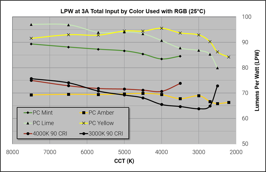
Figure 6 shows the lumens per watt performance for all configurations. Since all six of the measured fourth channel LED colors are phosphor-converted from the same type of blue LED die, the LPW data is similar to the total lumen performance.
Color Rendering Improvements
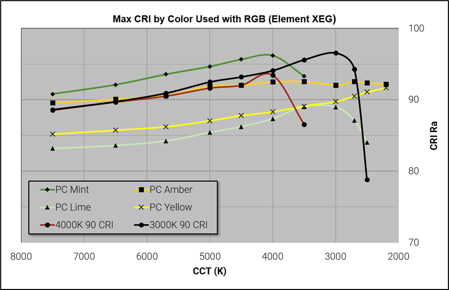
Each 4-channel configuration was tuned for the highest possible CRI Ra, as shown in Figure 7. PC mint yielded the highest CRI Ra of the group from 7500K to 4000K, where it was overtaken by the 3000K 90 CRI white LED. PC mint has a strong green phosphor output, which fills the middle of the spectrum and is complemented primarily by the red and blue LEDs. In warm white, this combination does not have enough red content to maintain a high CRI.
The 3000K 90 CRI white LED was boosted to 96.5 CRI at 3000K with the help of the direct red LED. However, the CRI plummets at 2700K and warmer. PC amber and PC yellow have the best CRI performance from 2500K to 2200K because they add broad-spectrum content in the 550 nm to 620 nm wavelength region, which is supplemented by the 625 nm red LED. PC mint and PC lime use a shorter-wavelength green phosphor that does not contribute as much to this region.
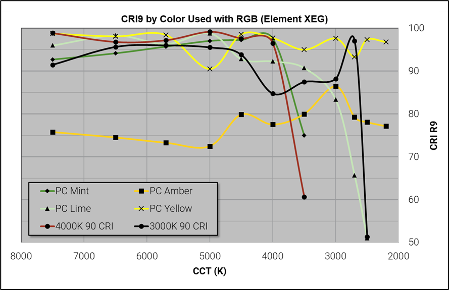
The spectra were not optimized for CRI R9, but we ensured all data points had CRI R9 > 50 as per the industry standard for 90 CRI LEDs. These data are shown in Figure 8. The trends here are less consistent because they depend on the spectrum of maximum CRI, but a few points can be made. PC yellow can consistently keep a high CRI R9 (> 90) from 7500K to 2200K. PC amber, although it had consistently high CRI, had a lower CRI R9 hovering between 70 and 80 for most of the CCT range. The other LEDs are rich in green phosphors and their CRI R9 drops sharply in warm white.
Comparison of Spectra
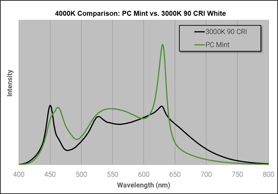
Figure 9 shows the 4000K spectra of the PC mint array and the 3000K 90 CRI white array (together with RGB). PC mint concentrates more photons near the peak sensitivity wavelength of the human eye (555 nm) by exchanging some royal blue photons for true blue and cyan photons, and especially limiting long-wavelength red (>640 nm). This lets PC mint outperform the 3000K 90 CRI white LED in LPW and total lumens.
PC mint also has a small CRI Ra advantage from 7500K to 4000K due to better matching with the reference curves. It loses this advantage at warmer whites because it cannot produce the long-red content needed to match warmer reference curves. Long-red wavelengths are prevalent in the 3000K 90 CRI white LED due to the red phosphor content.
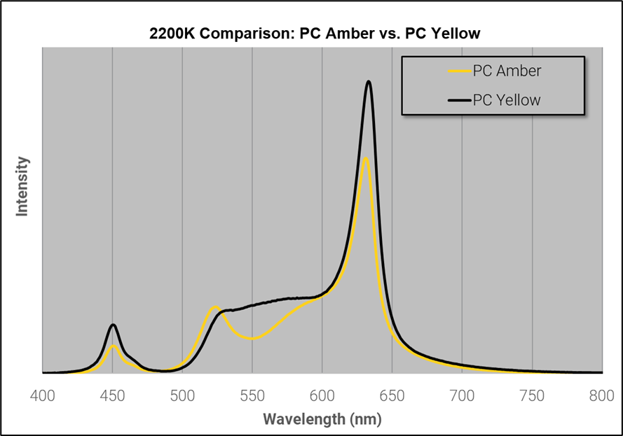
The 2200K spectra of the PC amber and PC yellow configurations are shown below in Figure 10. These two colors are the only configurations with enough 550 nm to 620 nm content to maintain high CRI Ra for CCTs ≤2700K. Both configurations yield about 92 CRI, but PC yellow has both higher LPW and higher CRI R9. PC yellow maintains better efficiency because it has more photons near the 555 nm sensitivity peak and relies more heavily on the red LED to produce the red content. The higher current for the red LED also leads to a higher CRI R9 due to greater red content near 650 nm. The PC amber LED has less efficient blue-to-red phosphor conversions because the amber phosphor emits longer wavelength light than the yellow phosphor.
Summary of LED Selection for Each Design Intent
It is difficult to choose any single LED as the best option to supplement RGB based on the complexity of the data set presented in this document. Since every application has differing requirements, here are some general recommendations:
- PC yellow and PC lime provide the highest output and efficacy if CRI Ra values in the 85-90 range are acceptable in the application
- For applications requiring CRI Ra values above 90, PC mint is the best choice for CCTs ≥3500K
- PC amber is the best choice for CRI Ra values above 90 across the full CCT range (7500K-2200K) if CRI R9 of 70 is sufficient
- White LEDs only outperform the phosphor-converted colors in specific CCT ranges, but they do also allow for easy, 1-channel white light output
- It is always more efficient to use all 4 LEDs to create white light, rather than relying on the single white channel, due to lower current density and better heat dissipation.
Please contact your Cree LED sales representative for more information or guidance on your unique color-mixing application. For questions or additional information on color mixing, please contact Cree LED at marketing@cree-led.com.
© 2023 Cree LED. All rights reserved. XLamp, the Cree logo and the Cree LED logo are registered trademarks of Cree LED.
Download a PDF of this Ap Note